
A solar installation without storage follows current generation: production peaks during the day while a substantial share of household demand occurs in the morning and evening. A battery changes that operating model. It stores surplus production, makes it available when needed, and can support critical circuits during a grid outage.
For a system designer, this means a battery cannot be selected by nominal capacity alone. Load power, required backup duration, usable depth of discharge, inverter compatibility, installation conditions, and future expansion all need to be considered together.
What defines a well-designed storage system
Reliable design starts with a clearly defined operating scenario. For backup applications, identify critical loads such as lighting, communications, heating controls, refrigeration, pumps, and essential workstations. For solar self-consumption, add the site’s typical generation and demand profiles.
Three connected parameters then need to be checked:
- Usable capacity, which defines the available energy reserve.
- Continuous and peak power, which determine whether selected loads can operate together.
- Expansion architecture, so future capacity does not require rebuilding the system.
Enclosure protection, operating temperature, and battery management are equally important. The BMS monitors cell voltage, current, temperature, and critical operating conditions. Coordinated communication between the BMS and inverter enables predictable charging, discharging, and state-of-charge reporting.
A8: a compact foundation with room to expand
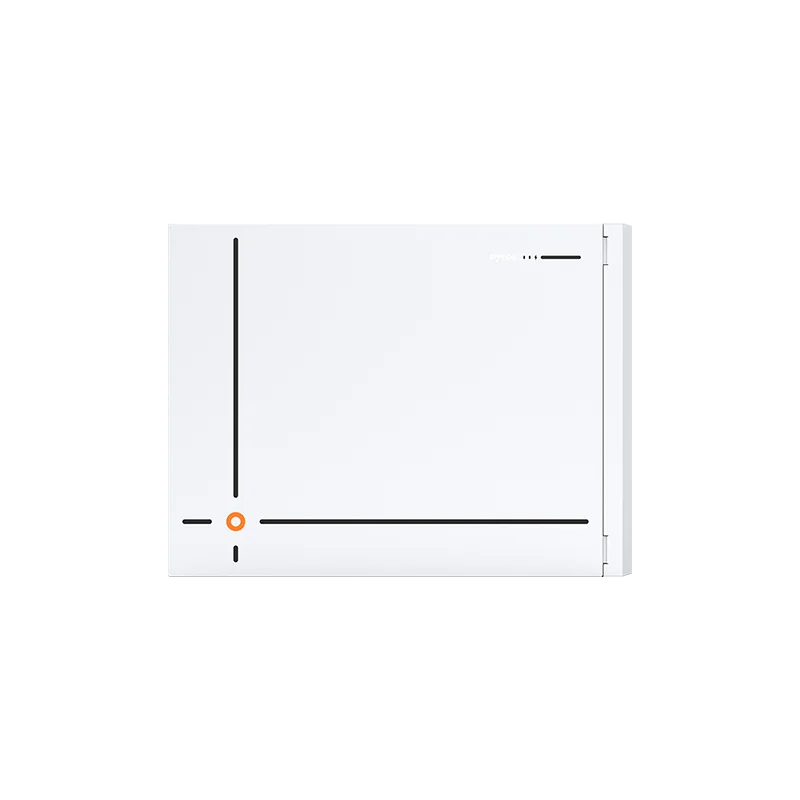
Pytes A8 is a low-voltage LFP battery with a nominal voltage of 51.2 V and 8 kWh of nominal energy. At the specified 80% depth of discharge, one unit provides 6.4 kWh of usable energy. It delivers 5.12 kW continuously and up to 6.7 kW for five seconds. This format suits critical household backup loads and smaller solar installations where a compact starting point and gradual capacity expansion are important.
A8 supports up to 16 units connected in parallel. Automatic slave-unit address allocation removes the need to configure DIP switches manually and simplifies commissioning as the system grows. CAN and RS485 interfaces enable closed-loop communication with compatible inverters, although the exact inverter model and protocol should always be confirmed during system design.
Key A8 characteristics include:
- 8 kWh of nominal and 6.4 kWh of usable energy at 80% DoD;
- 5.12 kW continuous output and up to 6.7 kW for five seconds;
- parallel connection of up to 16 units with automatic address allocation;
- integrated DC breaker, pre-charge circuit, and multi-layer overcurrent and short-circuit protection;
- an integrated aerosol fire suppression module;
- wall-mounted or floor-mounted installation.
The A8 enclosure is rated IP20, so it should be installed in a dry, controlled location protected from dust, weather, and accidental contact. The manufacturer specifies 4,000 cycles under test conditions of 25°C, 0.2C/0.2C, 80% DoD, and 70% end-of-life capacity. These conditions matter when comparing the published cycle figure with the intended operating profile.
Pi LV1: modularity and staged expansion
Pi LV1 addresses a different requirement. Its stackable architecture allows a project to begin with a base configuration and grow as site demand changes. This is useful when the owner expects to add solar modules, a heat pump, EV charging, or more backed-up circuits.
Modules are installed vertically, creating a predictable footprint without requiring an individual wall mounting point for each battery. Integrated connections reduce external cabling and help keep the installation organized.
Advantages for system integrators include:
- flexible total capacity;
- output power up to 10.24 kW;
- staged expansion within the same system concept;
- simplified inter-module connection;
- compact floor-mounted installation.
Choosing between the two platforms
A8 and Pi LV1 are not direct substitutes. A8 provides a compact 8 kWh starting module and expands through parallel connection within a low-voltage system. Pi LV1 emphasizes a stackable architecture, integrated inter-module connections, and predictable floor-mounted expansion.
The final choice should follow a load calculation and compatibility check for the selected inverter. Installation location, cable length, protection devices, backup topology, and operating logic should also be defined in advance. This approach produces a complete energy system with predictable behaviour, rather than simply a battery with the right capacity figure.